Technical drawings
Part of the design process
It is said "a picture says a thousand words." In history, cavemen and women drew sketches on cave walls to communicate their ideas. Today, sketching and drawing are an important stage in the design process. Drawings help communicate an idea so others can understand a design idea.
Isometric Drawings
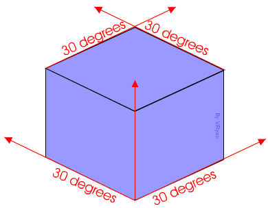
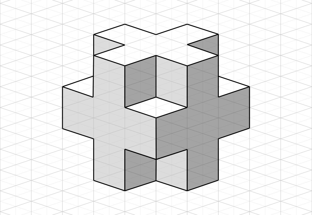
Isometric is derived from the Greek term "equal measure." An Isometric drawing is a way to show a design in three dimensions (xyz axis) on a 2 dimensional piece of paper. It creates a drawing that you would recognize as 3D - the object's length, width and depth are represented in the drawing to give a sense of real world scale and shape.
Important points about isometric drawings:
- Isometric drawings "distort" the view the object which can lead to misinterpretation
- Always begin drawing the front view of the object
- Lines are projected out at 30 degree angles
- Lines must be parallel with their adjacent lines (lines across from one another)
Part of the design process
It is said "a picture says a thousand words." In history, cavemen and women drew sketches on cave walls to communicate their ideas. Today, sketching and drawing are an important stage in the design process. Drawings help communicate an idea so others can understand a design idea.
Isometric Drawings
Isometric is derived from the Greek term "equal measure." An Isometric drawing is a way to show a design in three dimensions (xyz axis) on a 2 dimensional piece of paper. It creates a drawing that you would recognize as 3D - the object's length, width and depth are represented in the drawing to give a sense of real world scale and shape.
Important points about isometric drawings:
- Isometric drawings "distort" the view the object which can lead to misinterpretation
- Always begin drawing the front view of the object
- Lines are projected out at 30 degree angles
- Lines must be parallel with their adjacent lines (lines across from one another)
Source: http://www.technologystudent.com/prddes1/drawtec3a.png
|
Source: https://base12innovations.wordpress.com/tag/isometric/
|

Source: http://www.larapedia.com/engineering_quality_summaries/Isometric_view_and_orthographic_projection_engineering_drawings_clip_image004_0000.jpg
|
|
|
|
Source: https://www.youtube.com/watch?v=ZBuhGaGPYfQsource:
|
Source: https://www.youtube.com/watch?v=kYqn4QhUqe4
|
Orthographic Projections
Think of orthographic projections as "unfolding" the sides of a box
Think of orthographic projections as "unfolding" the sides of a box

Source: http://ftp.formz.com/images/products/formz/projection_objects/projects_1.gif

Source: Packpub.com
Orthographic Projection features
- Combines multiple 2D drawings to represent a 3 dimensional object
- A minimum of 3 Views are required to create an actual representation
- Views create an accurate representation so the object can be manufactured
- Standard views are front, top and right side and are drawn in that order
- Lines "project" (or extend) vertically and horizontally to connect the edges of the 3 views
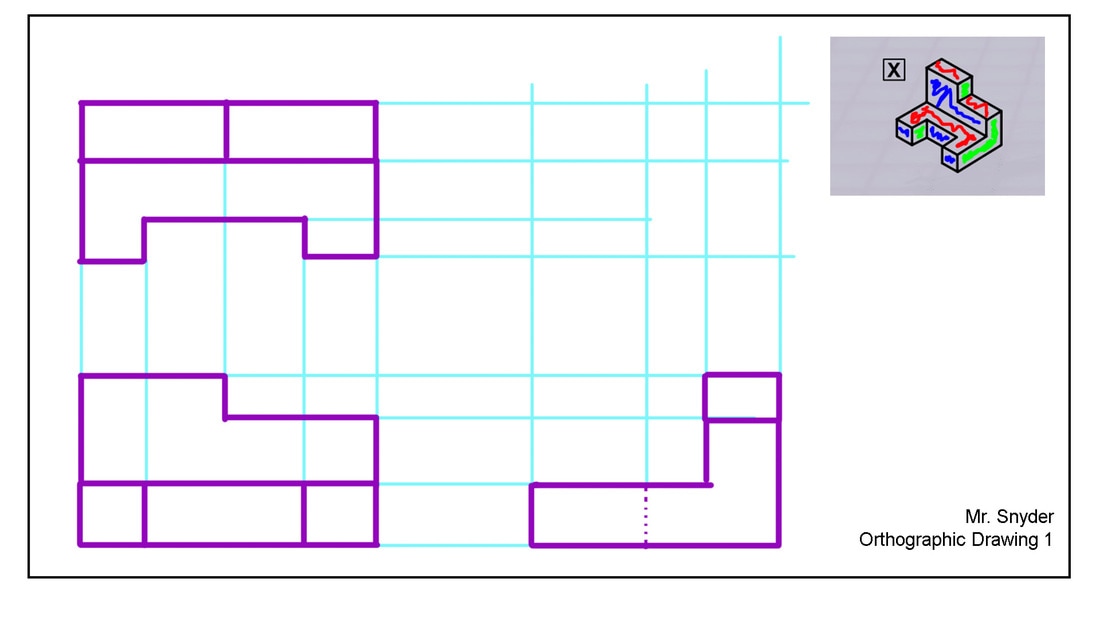
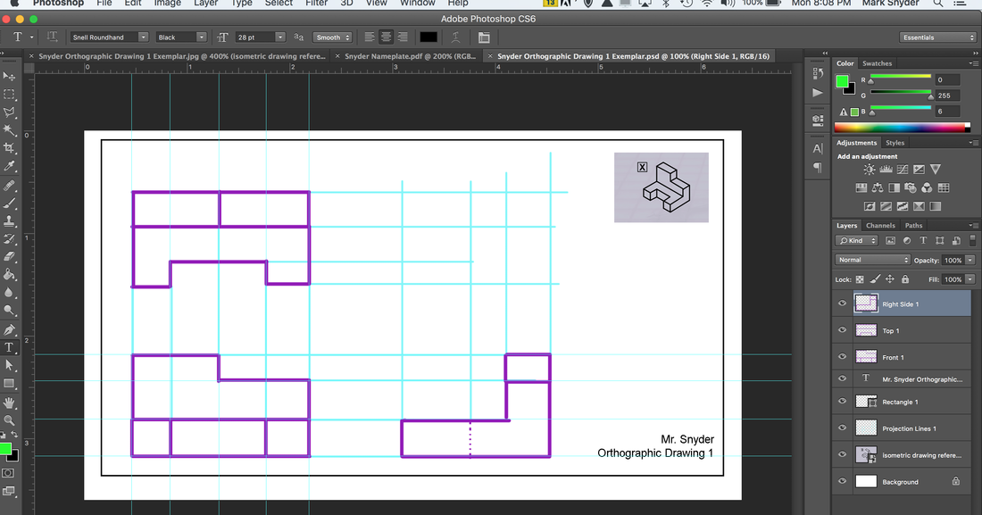
Orthographic Drawing
Isometric Drawing shown as an Orthographic Projection
Remember to use a separate layer in Photoshop.
Organize all layers for one drawing into a group and Name Ortho #
Isometric Drawing shown as an Orthographic Projection
Remember to use a separate layer in Photoshop.
Organize all layers for one drawing into a group and Name Ortho #
- Front
- Top
- Right Side
- Projection lines
|

|
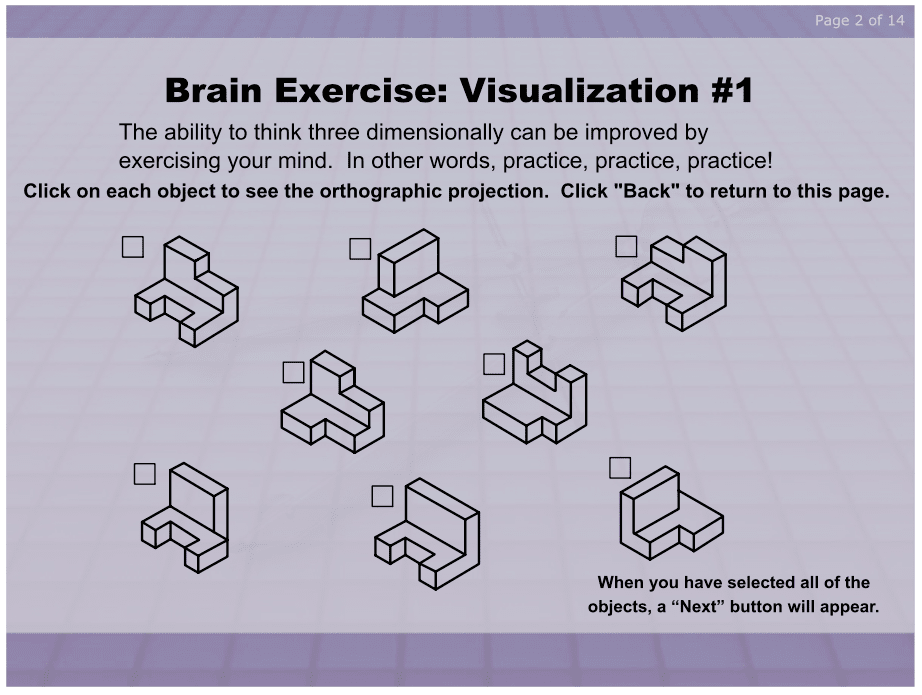
Practice!
Practice your orthographic visualization and drawing skills here.
Once you have drawn the orthographic projection on paper you can click on the shape to check you work.
Practice your orthographic visualization and drawing skills here.
Once you have drawn the orthographic projection on paper you can click on the shape to check you work.